18. Using a liquid crystal display
While using a computer to control and display results from a device is very powerful, it does result in the device being tethered to a computer in order to function. You may wish to have a stand-alone device. For such applications, portable liquid crystal displays (LCDs) are quite useful.
The LDC in your kit
The LCD in your kit can display 32 characters. Each character is represented in a block of pixels that is eight pixels tall and five pixels wide. The LCD display is based on the Hitachi HD44780 chip, which is very popular for small, low-cost, text-based LCDs. Fortunately, they are so popular that Arduino has built-in libraries for driving them, and we will put those to use.
Here are photos of the front and back of your LCD.
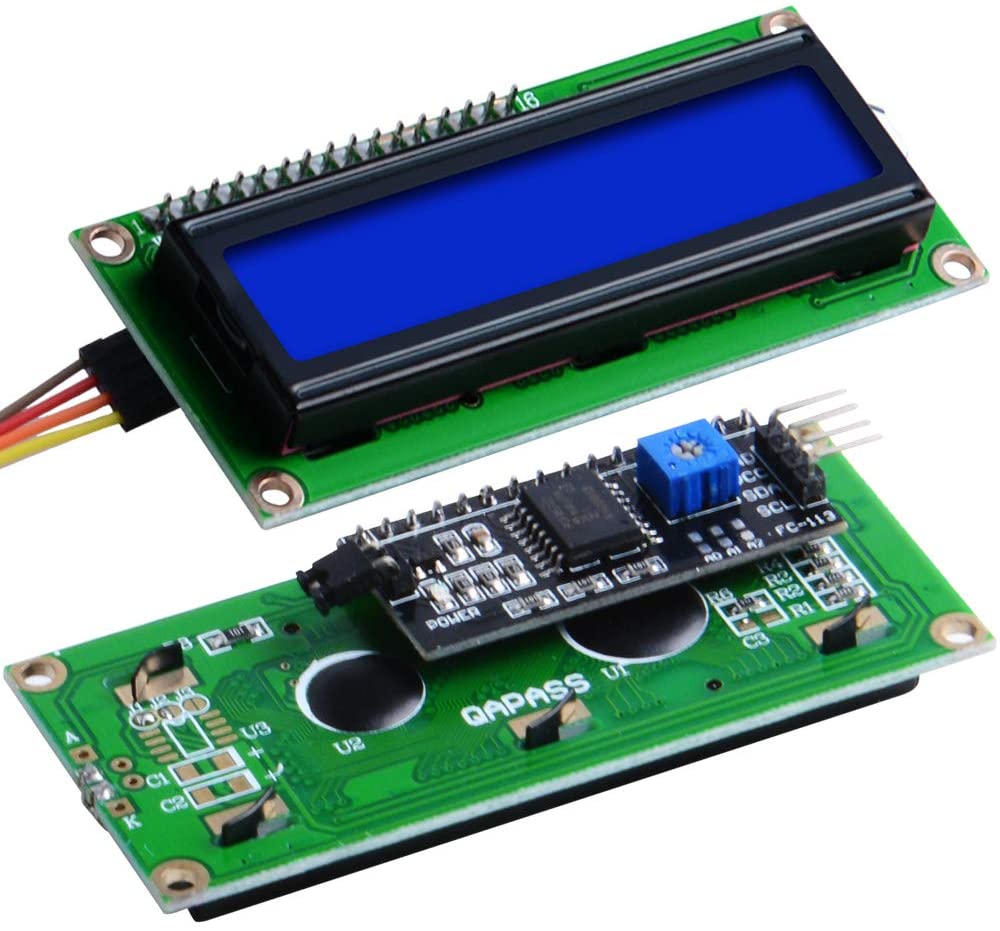
On the front (top photo) are 16 pins. In looking at the pinout on the Wikipedia page, you can see that many pins need to be connected to digital pins on the Arduino Uno in order to operate the LCD. Conveniently, though, the LCD in your kit contains a “backpack”, shown on the bottom of the two photos above. The backpack enables powering the LCD and connecting it to Aruino using I2C, which uses just two pins (SDA and SCL). Also on the backpack is a potentiometer, which you can tune using a small Phillips head screwdriver (there is one in your kit). The potentiometer adjusts the brightness of the display.
So, fortunately, we can use I2C to update the display of the LCD and we do not need to use many pins to do so.
Running multiple devices on the I2C bus
You can use I2C to control multiple peripheral devices. You simply need to supply the address of each. From the last lesson, you currently have a DAC set up for control over I2C. To demonstrate that we can control multiple devices, we will the MCP4725 DAC device connected. We will also connet the LCD. We will work through the rest of this lesson as a follow-along exercise.
Follow-along exercise 13: Using an LCD display
Set up the circuit below. You will add a potentiometer and the LCD to your setup from the last lesson. You may be able to leave your DAC setup as is, but you might need to move things around to keep wires tidy.

Our goal with this circuit is to have the flashing LED with the DAC running just as it did before. Separately we have a potentiometer that will adjust an input voltage to one of the analog input pins. The LCD will display the voltage, both in text and graphically. The reason we have these two essentially independent circuits at once is to demonstrate how to drive multiple devices using I2C.
Characters for the LCD
The LCD can display a set of characters
Driving the LCD
The address of the of the LCD is 0x27. (If you are trying to find the addresses of I2C devices you have wired up, this sketch is really useful!) We use the LiquidCrystal_I2C library to drive the LCD, so we need to be sure to #include <LiquidCrystal_I2C.h> in your sketch. It is also a good idea to #include <Wire.h> so that you can set your I2C speed to fast mode using Wire.setClock(400000), which will enable I2C
communication at 400k baud.
With that library included, you can instantiate an instance for communicating with the LCD using
LiquidCrystal_I2C lcd = LiquidCrystal_I2C(LCD_ADDR, nCols, nRows);
Here, LCD_ADDR is 0x27, the address of the LCD, and nCols and nRows are the number of columns and rows of blocks of pixels, respectively, in the LCD. For the onces in your kit, there are 16 columns and 2 rows. Once the lcd instance is in place, you need to initialize and backlight the LCD by calling
lcd.init();
lcd.backlight();
This should be done in the setup() function.
When using the LCD, you need to set the cursor position before writing a character. This is done using the lcd.setCursor() function. The first argument is the column position (starting at zero), and the second argument is the row position (also starting at zero). To write “Hello, world.” on the LCD on the first line starting to the left, you can do the following.
lcd.setCursor(0, 0);
lcd.print("Hello, world.");
The lcd.print() function is useful for printing strings. You can also define your own characters and write them using lcd.write(). The format of your own characters is a byte array of nCols 5-bit binary numbers. For example, to make an LA logo, you could define the character like this:
const byte LAlogo[8] = {
  B10000,
  B10000,
  B10010,
  B10101,
  B11111,
  B00101,
  B00101,
  B00101
};
To make this a character that the LCD can display, you need to call
lcd.creatChar(0, LAlogo);
The first argument is an integer that will stand for the character in calls to lcd.write(). You can specify up to eight characters, and they need to be numbered zero through seven.
To write this character a few places over on the second row, you would do:
lcd.setCursor(3, 1);
lcd.write(0);
We will make custom characters to represent a graphical display of voltage.
The sketch
Now that we have a basic idea of how to use the LCD, let’s look at the sketch, which you can go ahead and upload.
#include <Adafruit_MCP4725.h>
#include <LiquidCrystal_I2C.h>
#include <Wire.h>

// This is the I2C Address of the MCP4725, by default (A0 pulled to GND).
// For devices with A0 pulled HIGH, use 0x61
#define MCP4725_ADDR 0x62

// LCD address
#define LCD_ADDR 0x27

// Geometry of LCD
const int nRows = 2;
const int nCols = 16;

// Custom characters for LCD bars
const byte zeroBlock[8] = {B00000, B00000, B00000, B00000, B00000, B00000, B00000, B00000};
const byte twentyBlock[8] = {B10000, B10000, B10000, B10000, B10000, B10000, B10000, B10000};
const byte fortyBlock[8] = {B11000, B11000, B11000, B11000, B11000, B11000, B11000, B11000};
const byte sixtyBlock[8] = {B11100, B11100, B11100, B11100, B11100, B11100, B11100, B11100};
const byte eightyBlock[8] = {B11110, B11110, B11110, B11110, B11110, B11110, B11110, B11110};
const byte fullBlock[8] = {B11111, B11111, B11111, B11111, B11111, B11111, B11111, B11111};

// Frequency of oscillating signal
const int freq = 1;

// Delays for updating
const unsigned long sampleDelay = 20;
unsigned long lastSampleTime = 0;
const unsigned long reportDelay = 100;
unsigned long lastReportTime = 0;

// Sensor pin connected to potentiometer
const int sensorPin = A0;

// Instantiate the convenient classses for DAC and LCD
Adafruit_MCP4725 dac;
LiquidCrystal_I2C lcd = LiquidCrystal_I2C(LCD_ADDR, nCols, nRows);

void writeGraphicalVoltage(int x, int minX, int maxX) {
  /*
   * Graphical display of voltage on second row of LCD
   */
  float frac = ((float) (x - minX)) / (maxX - minX);
  int nBars = (int) (nCols * 5 * frac);
  int n5BarBlocks = nBars / 5;
  int fracBlock = nBars % 5;

  // Write the parts that are full blocks
  for (int i = 0; i < n5BarBlocks; i++) {
    lcd.setCursor(i, 1);
    lcd.write(5);
  }

  // Write fractional block
  if (n5BarBlocks < nCols) {
    lcd.setCursor(n5BarBlocks, 1);
    lcd.write(fracBlock);
  }

  // Write blank blocks
  for (int i = n5BarBlocks + 1; i < nCols; i++) {
    lcd.setCursor(i, 1);
    lcd.write(0);
  }
}


void setup() {
  // Set I2C to be fast mode
  Wire.setClock(400000);

  dac.begin(MCP4725_ADDR);

  // Initialize the LCD
  lcd.init();
  lcd.backlight();

  // Add the special characters for blocks
  lcd.createChar(0, zeroBlock);
  lcd.createChar(1, twentyBlock);
  lcd.createChar(2, fortyBlock);
  lcd.createChar(3, sixtyBlock);
  lcd.createChar(4, eightyBlock);
  lcd.createChar(5, fullBlock);

  // Label message on LCD
  lcd.setCursor(0, 0);
  lcd.print("Voltage: ");
}


void loop() {
  unsigned long currTime = millis();

  if (currTime - lastSampleTime > sampleDelay) {
    // Sinusoidal signal to DAC
    uint16_t x = (uint16_t)(4095 * (1 + sin(2 * PI * freq * millis() / 1000.0)) / 2.0);

    dac.setVoltage(x, false);

    lastSampleTime = currTime;

    // Report voltage to LCE
    if (currTime - lastReportTime > reportDelay) {
      // Read in and convert voltage
      int sensorValue = analogRead(sensorPin);
      float voltage = sensorValue / 1023.0 * 5.0;

      // Write the voltage on the first row (text display)
      lcd.setCursor(9, 0);
      lcd.print(String(voltage, 2) + " V");

      // Display the voltage graphically
      writeGraphicalVoltage(sensorValue, 0, 1023);

      lastReportTime = currTime;
    }

  }

}
The sketch should be self-explanatory since we have covered how to communicate with the LCD. Importantly the writeGRaphicalVoltage() function plots the voltage graphically on the second line of the LCD.
Note also that we have two devices connected to the same I2C bus and it is trivial to control them independently; we just have to set their addresses.
You can play with the potentiometer and watch the LCD change!