3. Hello, world. (a.k.a. Blink)
When you learn a new programming language, your first program is “Hello, world,” in which you make your computer print that global greeting to the screen.
In this class, we assume that you have a background in Python programming, so you know how to write the Hello, world program in Python.
[1]:
print("Hello, world.")
Hello, world.
We will now start exploring the Arduino IDE by writing the “Hello, world” of programmable electronics, blink.
Hardware for your first exercise
We will first discuss the three additional hardware components you need.
LEDs
In your kit, you will find many red light-emitting diodes (LEDs). An LED is a component that permits current to flow through it in one direction and emits light when it does. Here is a picture of one with a clear cover, though the ones in your kits will mostly have colored covers.
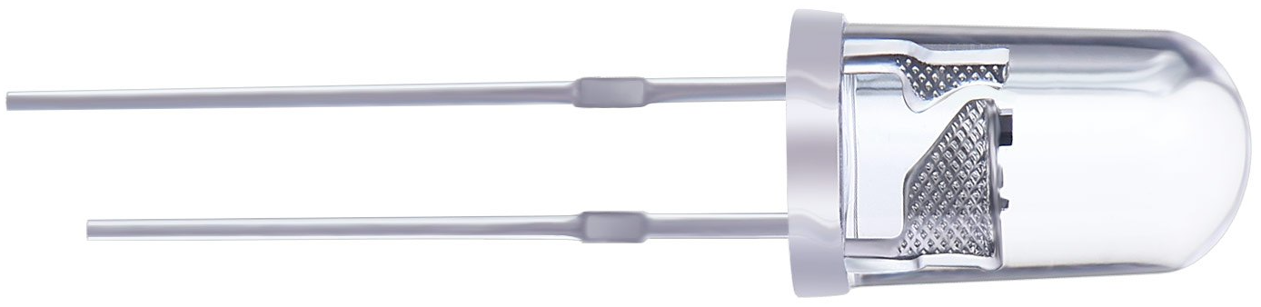
Because of the directionality of the diode, it is important that the LED is properly oriented. LEDs typically have one long lead and one shorter lead. The long lead is the anode, which you connect to the higher voltage, and the shorter lead is the cathode, which you connect to the lower voltage (ground). In drawings of LEDs, the long lead is typically shown as a bent wire.
You should also control how much current goes through an LED so you do not destroy it. LEDs are rated with a maximum forward current, which is the maximum continuous current an LED can safely pass. For many LEDs, including those in your kit, the forward current is 25 mA. They also have a forward voltage, which is the voltage drop across the LED. For the LEDs in your kit, the forward voltage is about 1.8 V. The maximum voltage that Arduino can provide is 5 V, so if you are powering your LED with Arduino, you will hit the forward current with a resistance of about 130 Ω by Ohm’s law. As such, if you use 220 Ω resistors with the LEDs in your kit, they should not burn out.
Resistors
You also have lots of resistors in your kits. Resistors contain insulating material that restricts the flow of electrons through them. Different resistors can have different composition, which will lead to different degrees of effectiveness in restricting current, or resistance, which is measured in ohms (Ω).
Resistors are color-coded for their resistance. The color-coding works in either four-, five-, or six-band codes. The resistors in your kit are either four- or five-band. Here is a picture of several four-band resistors (Evan Amos, public domain).
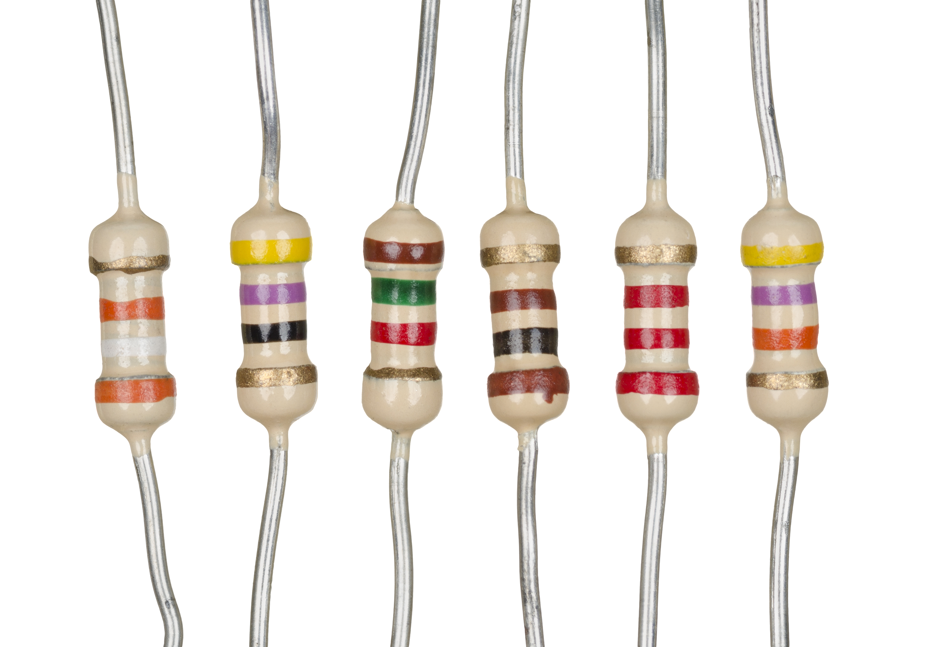
It can be hard to determine the direction in which to read the bands. In many resistors, the outer band that is closest to its respective lead is the first. In some four-band resistors, there is a larger gap between the third and fourth band. Finally, if there is a gold or silver band, it must be the last band.
Each color corresponds to a number, as follows.
Black
Brown
Red
Orange
Yellow
Green
Blue
Purple
Gray
White
Additionally, pink, silver, and gold are respectively –3, –2, and –1.
To read the value of resistance from the color bands for a four-band resistor, do the following.
The color of first band is the first digit.
The color of the second band is the second digit.
The color of the third band gives a multiplier as a power of 10. For example, if the color were orange, the multiplier is 10³.
The color of the fourth band gives the tolerance of the resistor. Here the number-to-digit system is not used. Gold and silver, meaning ±5% and ±10%, respectively, are the most often encountered colors of the fourth band.
So, to get the resistance, form a number with the first two bands, then multiply by the multiplier given by the third band. For example, a red-red-brown-gold banded resistor is 200 Ω with a ±5% tolerance.
To read the value of resistance from the color bands for a five-band resistor, do the following, very similar procedure.
The color of first band is the first digit.
The color of the second band is the second digit.
The color of the third band is the third digit.
The color of the fourth band gives a multiplier as a power of 10.
The color of the fifth band gives the tolerance of the resistor.
The 220 Ω resistor in the four-band example would have rings of red-red-black-black-gold.
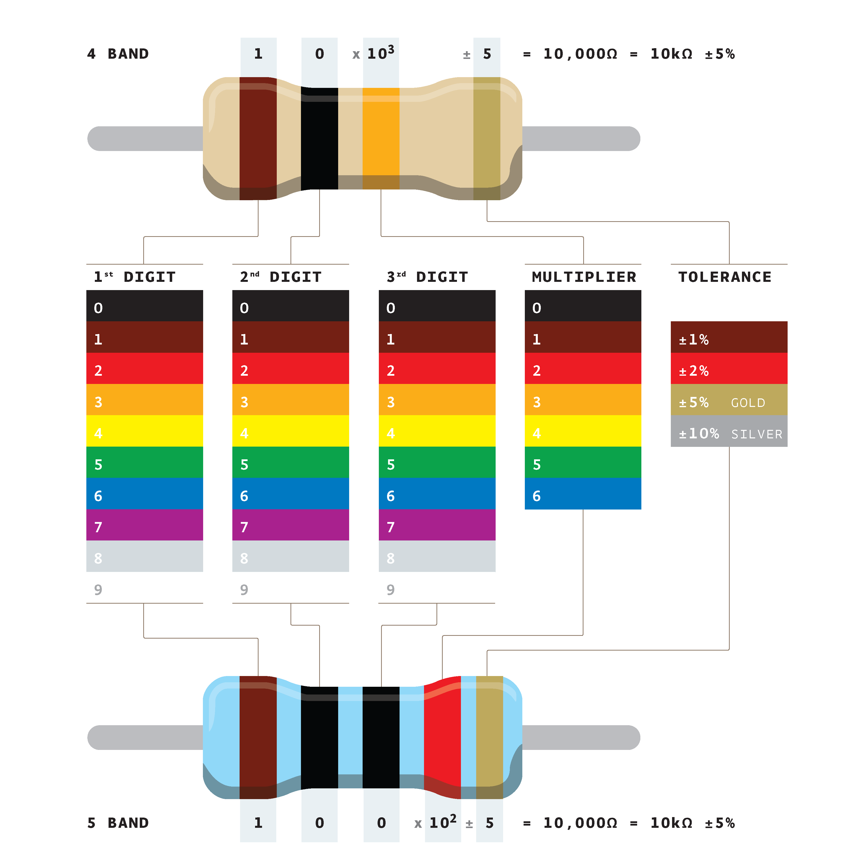
For reference, below is a diagram of resistor color codes (Adim kassn, CC BY-SA 3.0 licensed). To learn more about the color coding, see the Wikipedia page. For a handy color chart and resistance calculator, check out Digi-Key’s utility.
Thinking exercise 1: Resistor values
What four-band color pattern would I have for a 1±0.05 MΩ resistor? How about five-band?
I have a resistor with band colors yellow-purple-red-gold. What is its resistance?
I have a resistor of with band colors brown-black-black-brown-brown. What is its resistance?
The answers are at the end of this lesson.
Jumper wires
Jumper wires, also called jump wires, are plastic-coated wires that are used to connect components beyond the connections already present in the solderless breadboard. Jumper wires have different ends. The vast majority of jumper wires end in bare wires. Some specialized jumper wires have plastic ends that force the wire to rise orthogonally from where it is plugged in. Some of these special-ended jumper wires have male ends (exposed wire), or female ends (port for inserting wire).
Arduino sketches
Finally, before launching into the blink exercise, we need to discuss Arduino sketches generally. Arduino sketches are written in C++. If you know C or C++, the syntax will be familiar to you. If not, we will discuss syntax and concepts along the way as we work through the lessons.
Every Arduino sketch minimally has two functions, setup() and loop(). Upon upload of your sketch (or upon pressing the reset button on the board), the setup() function is run once. Then, the loop() function is run. When it finishes running, it runs again. And again and again and again. It keeps running over and over again until you upload a new sketch, press the reset button, or disconnect the Arduino. So, a minimal Arduino program is as follows.
void setup() {
}

void loop() {
}
It literally does nothing.
The content of the function, or any function in C++, should be contained in braces. When the brace that opens the code in a function is closed by a brace, that is the end of the function.
Note that void appears before both function definitions. This tells the compiler that these functions do not return anything. Note further that neither function takes any arguments. This must be the signature for setup() and loop() in any Arduino sketch.
Outside of setup() and loop(), you can define other functions and global variables and constants.
Follow-along exercise 1: Blink
With Arduino, we program a physical device. So, instead of printing something to the screen of your computer, you are going to make a physical device do something. For our first program, we will make an LED blink.
Wiring it up
The drawing below shows how to construct the physical device for the blink exercise.

In drawings like these, jumper wires are shown as lines (in this case, blue) connecting terminals on the Arduino and on the solderless breadboard. It is not important that you match the exact terminals on the breadboard, but you should get the connections right. Importantly, make sure that the anode (the long lead) of the LED is connected via the 220 Ω resistor to digital pin 6 of the Arduino.
In this circuit, digital pin 6 provides voltage driving current through the resistor, then through the LED, and finally to ground. In our Arduino sketch, we will change the output of digital pin 6 from high to low and back to high again to blink the LED.
Connecting the Arduino Uno to your computer
To connect the Arduino Uno to your computer, use the USB A/B cable. Once connected, you will see the ON built-in LED on the Arduino Uno light up. This indicates that the board has power.
You should now launch the Arduino IDE. You need to make sure the IDE and compiler know for which board you are compiling, so select the board by navigating the menus: Tools → Boards → Arduino Uno. (There may be sub-menus after Boards.) Next, you need to make sure your computer knows which port to use. Select Tools → Ports, and then the port to which Arduino is connected. On macOS, this may be something like dev/cu.usbmodem/146301. On Windows, this may be something
like COM4.
Coding your sketch
Fire up the Arduino IDE, and enter this code as your sketch.
// Identify which pin controls the LED
const int ledPin = 6;


void setup() {
  // Set the pin controlling the LED to output
  pinMode(ledPin, OUTPUT);
}


void loop() {
  // Turn the LED on, and then wait a quarter second
  digitalWrite(ledPin, HIGH);
  delay(250);

  // Turn the LED off, and then wait a quarter second
  digitalWrite(ledPin, LOW);
  delay(250);
}
I will now describe what this code does, step by step.
The first line of the program starts with //. This signifies a comment. The compiler will ignore any line that starts with //. You can also do comments that start with /* and end with */. For example,
/*
  all the stuff in here,
  even with multiple lines,
  is ignored.
*/
We start by declaring a global variable ledPin to be 6. We have connected the LED up to pin 6, so we need to make sure Arduino knows this. In front of the declaration, we have the keyword int. This designates ledPin to be of integer type. Any variable in an Arduino sketch needs to have its type declared. We also have the keyword const, specifying that this variable is a constant. This is not necessary, but is good practice for a variable whose value will never change in
your sketch (not least because it saves RAM; const variables are stored safely in flash memory). Finally, note that the line ends with a semicolon. All statements in a sketch must end with a semicolon.
Proceeding to the setup() function, we set up the pin controlling the LED so that it can output voltages. By default, all pins on an Arduino Uno are inputs. That is, they expect to receive a voltage signal that they then send to the ATmega328 microcontroller. If you want a pin to serve as an output, as we do here, we need to set the mode of the pin. We do this using the pinMode() function. You can read about it
here in the extremely useful Arduino language reference. (Seriously, bookmark the reference.) pinMode() has return type void, which means it does not return anything, so you simply call the function with an assignment operation. I.e., do not do something like this: ledPin = pinMode(ledPin, OUTPUT). The first argument is
the pin whose mode you want to set. The second argument is either INPUT or OUTPUT. In our case, we want OUTPUT, since we are outputting a signal to the LED.
Now, we turn our attention to the loop() function. We start by using the digitalWrite() function to set the pin connected to the LED to HIGH. Remember, pin 6 is a digital pin, so it can only take on two values, zero (LOW) or five volts (HIGH). digitalWrite() takes two arguments, the first bring the pin to which you want to write. The second argument must by HIGH or LOW. So, the digitalWrite(ledPin, HIGH) statement results in a 5V potential across the LED,
thereby turning it on.
Next, we use the delay() function to tell the microcontroller to just hang out for a while and do nothing. The argument of delay() is the amount of time in milliseconds that you want to wait. We chose 250 milliseconds to wait a quarter second, which will ultimately give a flash at a frequency of 2 Hz.
After the delay, we need to turn the LED off, so we use digitalWrite(ledPin, LOW). We again wait 250 milliseconds.
When the loop() function ends, it starts again. So, after waiting 250 ms, the loop function gets called again and the LED is turned on again.
Aside: The Arduino core libraries
We used pinMode(), delay(), digitalWrite(), INPUT, OUTPUT, HIGH, and LOW in the above program. These were not defined anywhere in the sketch. This is because they are included in the Arduino core libraries, which are included by default in any Arduino sketch. The functions included in the core libraries are included in the Arduino language reference. (Do
you see a trend here? This is an exceptionally useful website!)
Saving the sketch
After you have completed your code, you need to save the sketch. We will name our sketch blink. When you save an Arduino sketch it must be in a folder having the same name as your sketch. The Arduino IDE will automatically create this folder when you select Save from the File menu. Within the folder is a text file with the suffix .ino that contains the code of your sketch. In this case, the file is called blink.ino. You can have other files in the folder, including other
.ino files, files with C++ code, and header (.h) files. This is a bit more advanced than what we will encounter in this class, so you do not need to worry too much about that extra files in the sketch folder.
Uploading the sketch and blinking!
Now that you have saved your sketch on your computer, you can upload it. To compile the sketch to make sure everything is ok, you can click the check mark icon on the top left of the Arduino IDE window. To (re)compile and upload your sketch, click on the right arrow icon next to the check mark icon. The black window at the bottom of the Arduino IDE window will show you messages from the compiler. If you see red text, you know something when wrong. Be sure to carefully read any messages; they will help with debugging.
After clicking the arrow, if everything went according to plan, the sketch will be compiled and uploaded to the Arduino Uno, and the light will start blinking!
Answers to thinking exercise
A 1±0.05 MΩ resistor would have brown-black-green-gold for a four-band color pattern and brown-black-black-yellow-gold for a five-band color pattern.
This is a 4.7 kΩ (with a 5% tolerance) resistor.
This is a 1 kΩ (with a 1% tolerance) resistor.