2. A tour of Ardiuno Uno and the solderless breadboard
Let us get acquainted with your Arduino board. Take out your Arduino board, a large (64-row) solderless breadboard, and holder, and let’s get started!
Setting up your Arduino and breadboard
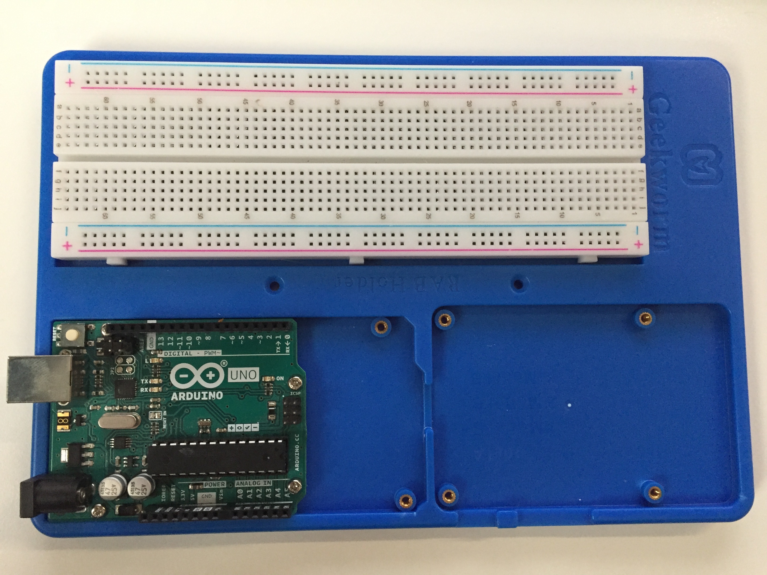
Take out one of your long solderless breadboards; the long ones have 64 terminal strips (rows of holes). Also remove your Arduino Uno from the box. If it has a plastic holder included in the box, you can leave that in the box; you will not need it for this course. Finally, remove your RAB holder from its packaging. At the completion of this section, you should have something that looks like this:
Peel the nonstick coating off of the back of the solderless breadboard.
Stick the breadboard into its place in the holder. By convention, I like to have the positive (red) bus strip nearest to the Arduino Uno, but it does not matter.
Screw the Arduino Uno into the holder. You should not have a problem screwing in the four screws. For some cheaper holders, the holes in the Arduino Uno may not exactly match the holder. That should not be a problem for you, but do not force screws in if the alignment is off.
A tour of a solderless breadboard
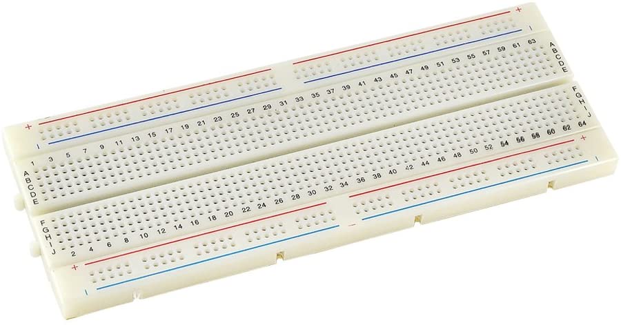
In reading this section, it will help to look at the picture above. The solderless breadboard shown above has 840 holes, called terminals into which you can stick leads of components. How are these terminals connected?
The two sets of terminals labeled with a red + and a blue – are referred to as bus strips. These are the strips that provide power to the components of the board. All of the terminals along the red line are connected to each other. All of those along the blue line are also connected to each other. In both cases, that is all they are connected to. So, if you want to provide power to components, you connect a voltage source to one of the terminals of the red strip, and all of the
terminals on the strip are then connected to the voltage source. Similarly, if you connect one of the terminals in the blue strip to ground, then all of the terminals in the blue strip are connected to ground
The bus rails at the top of the image are similarly connected. Note that none of the bus rails are connected to each other.
Now, let’s look in the middle of the breadboard, the terminal strip. You will notice that, based on the markings of the breadboard, each terminal as a unique letter-number address. a1 is the terminal on the top right of the image and j64 is at the bottom left. the terminals are connected as follows. a#, b#, c#, d#, and e#, where # denotes a number (e.g., 17), are connected. f#, g#, h#, i#, and j#, are also connected. There are no other
connections. You will notice a gap (called a ravine) that separates rows a though e from rows f through j. (The ravine is just the right width so that an integrated circuit chip (IC) can fit perfectly over the ravine. You will learn more about this in a later lesson.) So, if we view letters as indexing columns and numbers as indexing rows, then the first five terminals in a row are connected, and the last five terminals in a row are connected. There are no other connections
within the terminal strip.
Note that some breadboards have a gap in the connections of the bus strips. An example is shown below.
The breadboards in your kit should now have a gap in the bus strip, but gapped bus strips are rather common, so you should always check.
To better understand the connections in a solderless breadboard, we can look at the breadboard with the backing removed, shown at right below (image from a Sparkfun tutorial by M-SHORT and JOEL_E_B, CC BY-SA-4.0 licensed).
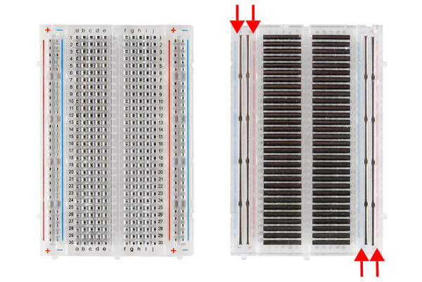
The bus strips are labeled with red arrows. Now, let’s take a look at the strip of clips that make up the terminals. Pictured below is a single strip from connected terminals (image also from the same Sparkfun tutorial by M-SHORT and JOEL_E_B, CC BY-SA-4.0 licensed). You can see from the springy pincher-like design that the breadboard is well suited for repeat insertion and removal of components.

A tour of the Arduino Uno
We continue our tour of the essential pieces of our prototypes with the Arduino Uno. Throughout the course, we will probably refer to the board simply as “Arduino” for short, not to be confused with the Arduino IDE. The board you will use is an Arduino Uno (Revision 3). A labeled schematic of the board is shown below, and you should refer to it as well as your physical Arduino Uno in the following discussion.

In looking at the schematic, you will notice that not all of the components on the Arduino appear. Nonetheless, all of the important ones that you need to know about to do your projects are shown. The built-in LEDs and pins are labeled on the Arduino Uno itself and on the schematic, and I will discuss those in a moment.
Components of the Arduino Uno
For now, I will focus on the components that are labeled with text outside of the area of the board, going counterclockwise, starting with the microcontroller.
ATmega328 microcontroller: This is the central nervous system of the board. Compiled code is loaded onto this chip and as it is executed, the chip sends and receives appropriate signals from the pins of the Arduino. I give more details on this component in the following section.
unconnected pin: The unlabeled pin on the Arduino Uno is not connected to anything. It is only there for compatibility with future versions of the board.
DC supply input: This is one of three ways you can deliver power to the Arduino Uno. The jack fits a 2.1mm DC Plug, and any DC power supply between 6 and 20 V may be used, but between 7 and 12 V is recommended. You will most likely not use this input, since you will almost always have your Arduino connected to your computer via the USB port, which also supplies power.
5V voltage regulator: The regulator takes the input from the power supply and delivers 5V to the Arduino.
quartz timing crystal: Having a reliable clock is essential for the functioning of the microcontroller. The quartz timing crystal delivers reliable timing.
USB interface chip: This chip does the calculations and data conversions necessary for communication via USB with external devices (almost always your computer). The maximum supported baud rate for sending and receiving data over USB is 115,200 baud (1 baud = 1 bit/second).
USB port: This is where you insert the “B” end of the USB cable you will use to connect your computer to the Arduino Uno. This allows data to be exchanged between the Arduino and your computer. It also doubles as a power supply. When connected via USB, the Arduino does not require another power source.
SCL and SDA pins: I will discuss these when I discuss the labeled pins in a subsequent section.
The ATmega328 microcontroller
To program an Arduino, you write Arduino-flavored C++ code, called a “sketch,” on your computer using the Arduino IDE, and then that code is compiled using ARV-GCC, a compile specific to microcontrollers made by the company that makes the ATmega328. The compiler is included in the Arduino IDE. The compiled objects are uploaded onto the ATmega328 microcontroller. The program is then run on the board.
The ATmega328 microcontroller can be thought of as a mini-computer. It has the following components.
An 8-bit central processing unit (CPU). It is capable of performing about 20 million instructions per second.
2 kB of static random access memory (SRAM). This is the RAM that is utilized when running your sketch.
32 kB of flash memory (also called program memory). This is where the compiled program code is stored. Also stored in flash memory is the bootloader, which is what allows changes to the flash memory. You can write to flash memory if you know how, but for now, don’t even think about it. There are many ways that can go wrong and brick your Arduino.
1 kB of electrically erasable programmable read-only memory (EEPROM). This is kind of like a hard disk. It is memory that code running on the microcontroller can read from and write to. Unlike SRAM, but like flash memory, data stored in EEPROM persists even when the Arduino is powered down. EEPROM is usually used to store configuration information. We generally will not use EEPROM, opting instead to send data via USB to the computer and store it there.
23 general purpose input/output ports. This allows the microcontroller to read in voltages from pins on the Arduino as well as write voltages to those pins.
A universal synchronous/asynchronous receiver/transmitter (USART). This takes bits of data and communicates them (either reading or writing) serially. The USART connects with the USB interface chip to communicate serially over USB with your computer.
An inter-integrated circuit (I2C or I²C) interface. This two-wire interface is primarily used to communicate with peripheral devices. The default for data communication is 100 kbaud (100,000 bits per second), but this can be increased to 400 kbaud. The acronym is either pronounced “I-squared-C” or “I-two-C.” I2C communication will be discussed later in this lesson.
A serial peripheral interface (SPI) port. This is also used to communicate with peripheral devices and requires four wires. It is significantly faster than I2C, achieving about 15 Mbaud (15 million bits per second) on Arduino. SPI communication will be discussed later in this lesson.
A six-channel 10-bit analog-to-digital converter (ADC). When an analog signal comes in, e.g., a voltage, it needs to be converted into digital data to be stored. The 10-bit converter converts a voltage between zero and five volts to a 10-bit integer (that is, an integer between 0 and 1023). The ADC on the ATmega328 can accept signal from six channels. Each conversion of an analog voltage to a digital number takes about 110 µs, but this can be reduced about ten-fold with some trickery involving the clock.
Two 8-bit and one 16-bit timers. The timers are referred to as Timer0, Timer1, and Timer2, with Timer1 being the 16-bit timer.
Built-in LEDs
The four built-in LEDs in the above schematic have the following functions.
ON: This LED is on when the Arduino has power.
L: This built-in LED is on whenever digital pin 13 is set to
HIGHand off when it is set toLOW. This LED is referred to as theLED_BUILTINin theArduino.hlibrary. (We will discuss the library when we start talking about sketches in a future lesson.)TX: This LED is on when data are being transmitted via USB.
RX: This LED is on when data are being received via USB.
You will see the TX and RX LEDs light up when you upload sketches, and the Arduino is communicating via USB with your computer.
ICSP headers
The Arduino Uno features two in-circuit serial programming (ICSP) headers, each with size pins. These headers are used for in-system programming (ISP) using a protocol that uses SPI communication. This is how chips are programmed in the factory. ICSP1 provides the ability to do ISP for the ATmega328 microcontroller and ICSP2 provides the ability to do ISP for the USB interface chip.
ISP allows programming the microcontroller without using the bootloader or Arduino IDE. It is usually used when the bootloader somehow gets damaged or erased, for example if you are attempting to write to flash memory against the advice I gave above. Similarly, if there is damage to the USB interface chip, you can use the ICSP2 interface to reprogram it.
Because the pins of the ICSP1 are used for SPI communication with the ATmega328 microcontroller, some of the pins are identical to digital pins elsewhere on the Arduino. In the schematic diagram of the Arduino, we number the pins on starting from the top left (right next to number 1 in the schematic) and continue going clockwise to label the pins 1 through 6. Pin 1 on the ICSP1 is equivalent to digital pin 12 on the Arduino, ICSP1 pin 3 is equivalent to digital pin 11, and ICSP1 pin 6 is
equivalent to digital pin 13.
We will not be using the ICSP headers in this class, but it is good to be aware of them.
Pins on the Arduino Uno (Rev3)
The pins on an Arduino Uno each have specific features, and I will describe them here. It is worth looking at the detailed pinout diagram, reproduced below, as well. Since the schematic is far up the page at this point, I reproduce it here for ease of reference while describing the pins on the Arduino Uno.
Not counting the unconnected pin, Arduino has 31 pins, plus two sets of SPI communication. Some of the pins are redundant, going to exactly the same pin on the ATmega328 microcontroller. Some pins have multiple functions. Some pins may not be used at the same time for different purposes. All these may begin to look intimidating now, but don’t worry, we will start simple and work from there.
Because I would like this lesson to serve as a useful reference, I will include descriptions of some pins that use terms that may still be unfamiliar. In particular, I will refer to some functions in the Arduino library,
Power pins
3V3: This power pin is set to 3.3V. You can use it to power peripheral devices that need to run on 3.3V.
5V: This power pin is set to 5V. This is the pin you most often use to deliver power to peripheral devices via the solderless breadboard.
GND: There are three GND pins, two next to the 5V pin and one on the opposite side of the board next to digital pin 13. GND is short for “ground,” which is the reference voltage to which all other voltages are relative. By convention, this is zero volts.
VIN: This pin is set to the voltage provided by the DC supply input, if it is used. It is therefore not 5V, and may be substantially larger.
Digital pins
The pins labeled 0 through 13 are digital pins, meaning that they can only read and write binary data. When they are being used to read input voltages, if the voltage is above a 3V threshold, it reads HIGH, and if it below that threshold, it reads LOW. Similarly, they can only write low (0V) or high (5V) voltages.
No pins on the Arduino Uno can write analog voltages. To write analog voltage, you need an external digital to analog converter (DAC). We will discuss those in a future lesson. To approximate writing analog voltages with a digital pin, you can use pulse width modulation (PWM). PWM, which requires use of one of the three timers in the ATmega328 microcontroller, is accomplished using the perhaps confusingly named analogWrite()
function in your sketches. Digital pins marked with a tilde (~) can use PWM.
In the list of digital pins below, each one has read and write digital signals, but has additional features in the description.
Digital pin 0: This pin is used for receiving serial data. If you are doing any serial writing in a sketch, this pin should be left unoccupied.
Digital pin 1: This pin is used for transmitting serial data. If you are doing any serial reading in a sketch, this pin should be left unoccupied.
Digital pin 2: This pin may be used for interrupts with interrupt number
0. We will discuss interrupts in a future lesson.Digital pin 3: This pin does PWM using Timer2. Because the
tone()function also uses Timer2, PWM may be disrupted iftone()is used on pin 3. This pin may be used for interrupts with interrupt number1.Digital pin 4: This pin connects to an external clock. This is only used when doing synchronous receiving/transmitting of serial data. By default, the Arduino Uno does asynchronous receiving/transmitting of data, and you will not need to do synchronous data transfer in this class, so you do not need to worry about this issue when using this pin.
Digital pin 5: This pin does PWM using Timer1.
Digitial pin 6: This pin does PWM using Timer0. It is also used in the microcontroller’s analog comparator. If the input of digital pin 6 is higher than that of digital pin 7, the comparator is set to high. If the input of digital pin 6 is lower than that of digital pin 7, the comparator is set to low.
Digital pin 7: This pin is used in the microcontroller’s analog comparator. If the input of digital pin 6 is higher than that of digital pin 7, the comparator is set to high. If the input of digital pin 6 is lower than that of digital pin 7, the comparator is set to low. You will no need to use the comparator function in this class.
Digital pin 8: This pin is used in input capture, where a time stamp is recorded when an input comes in. It an also be used to output the system clock of the ATmega328. Both of these functions require programming a fuse in the ATmega328, which is beyond the scope of this course.
Digital pin 9: This pin does PWM using Timer1.
Digital pin 10: This pin does PWM using Timer1.
Digital pin 11: This pin does PWM using Timer2. It is also the MOSI pin of the SPI. It is equivalent to pin 4 on the ICSP1 header. (SPI is explained below.)
Digital pin 12: This pin is the MISO pin of the SPI. It is equivalent to pin 1 on the ICSP1 header. (SPI is explained below.)
Digital pin 13: This pin is the SCK pin of the SPI. It is equivalent to pin 3 on the ICSP1 header. When it is
HIGH, then LEDLis illuminated, and when it is low, LEDLis not illuminated.
Analog input pins
The six analog input pins are connected to the ATmega328 microcontroller’s analog-to-digital converter (ADC). So, any input voltage into the analog input pins can be read and converted to a 10-bit integer using the analogRead() function. Additionally, all six of the analog input pins can function as digital I/O pins like those described above, though none of them can do pulse width modulation.
Pin A0: Also digital pin 14.
Pin A1: Also digital pin 15.
Pin A2: Also digital pin 16.
Pin A3: Also digital pin 17.
Pin A4: Also digital pin 18. This pin also served as the SDA for I2C communication. It connects to the same pin on the ATmega328 microcontroller as the pin labeled SDA in the above schematic. Functionally, these two pins are identical. I2C communication is described later in this lesson.
Pin A5: Also digital pin 18. This pin also served as the SCL for I2C communication. It connects to the same pin on the ATmega328 microcontroller as the pin labeled SCL in the above schematic. Functionally, these two pins are identical. I2C communication is described later in this lesson.
Other pins
IOREF: This pin is used as a voltage reference for shields. Shields are boards that can be plugged directly into the Arduino. For example, here is a shield used to control motors. The IOREF pin provides a shield access to the voltage of the board, including boards with the same footprint as the Arduino Uno that may not operate at 5V. The IOREF pin on the Uno is always set to 5V.
RESET: If you set this pin to
LOW(connect it to ground), it is equivalent to pressing the RESET button.AREF: This pin serves as an analog reference. An external voltage is plugged in here and used as a reference for analog-to-digital conversion (ADC). By default, the operating voltage of 5V is used, and that will suffice for us in the course. You can read a blog post on using the AREF pin.
I2C communication
Inter-integrated circuit (I2C), sometimes referred to as “two-wire interface,” communication is accessible via the serial data line (SDA) and serial clock line (SCL) pins. To communicate data over I2C, the voltage on the SCL switches between high and low values in regular intervals timed by the clock. The SDA also switches at the same frequency. A voltage comparison is made on each cycle, and if the SDA voltage is low relative to that of the SCL, the bit is a zero, and is one otherwise, as shown in the sketch below.

Many external devices use I2C for their communication, including the MCP4725 DAC we will use on a breakout board.
On the Arduino Uno, the SDA and SCL pins are used for I2C communication. The maximum speed of I2C communication is about 400 kbaud, though by default the speed is 100 kbaud. The SDA and SLC pins are functionally equivalent to the A4 and A5 pins, respectively.
SPI communication
Serial peripheral interface (SPI) communication with Arduino is possible. In SPI communication, one device (almost always the Arduino Uno) is the primary device, and any other connected devices are secondary devices. The primary device can ask for and receive data from a secondary device and can also send data to a secondary device. A secondary device can send data to or receive data from the primary device.
Note that in almost all of the documentation you see, the primary device will be referred to as a “master” device and secondary devices are referred to as “slave” devices. The pins are described by acronyms. MOSI, which means “master-out-slave-in,” means that the primary device sends data out to a secondary device. MISO, which means “master-in-slave-out,” means that the primary device receives data sent from a secondary device. We will use the terms primary and secondary because of the obviously awful connotations of the master/slave terminology. Nonetheless, we will use the MOSI, MISO, and SS acronyms because they appear on pinout diagrams for SPI devices.
SPI communication requires a MOSI, MISO, and system clock (SCK) connection. On the Arduino Uno, you would use digital pins 11, 12, and 13, respectively. Alternatively, you can respectively use ICSP1 pin 4, ICSP1 pin 1, and ICSP1 pin 3. The wires coming out of these pins can connect to multiple external devices, and each device using SPI communication needs to be connect to these three pins.
The fourth pin necessary for SPI communication is the secondary select (SS) pin. Each secondary device has its own SS pin, and any digital pin on the Arduino Uno can serve as an SS pin. When using SPI communication, the microcontroller shuts down the SS pins of all secondary devices it is not communicating with, enabling it to communicate with one secondary device at a time.
SPI is much faster than I2C, and can operate at about 15 Mbaud on Arduino Uno.
Arduino pinout
The Arduino pinout is shown below. If your broswer does not support embedded PDFs, you will not see it below, but you can see the document here. It is copyright Arduino, licensed under a CC-BY-4.0 license.