24. Transistors
Transistors are key components of almost any modern circuit. They have myriad applications, and are included in pretty much all of the integrated circuits you have already been introduced to, including analog-to-digital converters, digital-to-analog converters, and op-amps. Horowitz and Hill go so far as to say that “The transistor is the essential component of every electronic circuit.” In this lesson, we will explore using transistors as switches.
Basic concepts behind transistors
We will not go into the details of the (Nobel Prize-winning) physics behind how transistors work, but will treat them from a practical perspective. Transistors are three-terminal components. They come predominantly in two varieties, bipolar junction transistors (BJTs) and field effect transistors (FETs). These two varieties of transistor vary in their mode of construction and in other meaningful ways in their operation that we will not spend much time on. FETs are dominant in electronics these days, including in the integrated circuits mentioned above, but BJTs are still widely used. Importantly, both varieties have the same two salient features.
Transistors have a polarity, with one end set at a higher voltage than the other during normal operation.
Charge is transported from one terminal electrode to another under control of a third electrode.
Transistors are active in the sense that the output signal they can produce is greater than an input (control) signal.
The details of how transistors work is very interesting and worth delving into if you have the time. You can start with the Wikipedia pages for BJTs and FETs.
Bipolar junction transistors as switches
We only have a few FETs, but we do have both varieties of BJTs, npn and pnp. The difference in ordering of the constitutive layers of the transistors results in reversed polarities. Here, “n” means that the semiconductor is doped in such a way that there are an abundance of free electrons. Current flow in n-type material consists predominantly of electrons moving in response to the voltage difference across the material. Conversely, “p” means that the semiconductor is doped in such a way that there are an abundance of free “holes.” You can think of the “holes” as a deficit of electrons. Current flow in n-type material consists predominantly of “holes” moving in response to the voltage difference across the material.
Below is the schematic symbol for BJTs (though they are sometimes drawn with a circle around them).
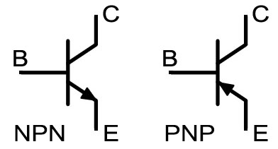
The labels C, B, and E refer to collector, base, and emitter, respectively. In this exercise, we will use npn BJTs. They are labeled 2N3904. Do not confuse them with the pnp BJTs.
For an npn, the current flows from collector through emitter; the collector must be more positive than the emitter. (The opposite is true for a pnp.) The current flowing through the collector is approximately \(I_C = \beta I_B\), where \(\beta\) is the gain, typically around 100. (This is an approximation of a result from the Ebers-Moll model.) Note, though, that because the collector must be more positive than the emitter, the transistor reaches saturation above a given input current \(I_B\).
So, if the input current is sufficiently high, the transistor operates at saturation and the current through it is set by the resistance of the load (that is the current that would be there if the load was connected to ground and not through the transistor). When the base current is zero, then no current flows through the transistor. In such a way, the transistor can function like a switch.
There are countless other applications of transistors, especially when used with feedback, but we will just use them as switches. This is not too restrictive; as Horowitz and Hill put it, “If you took a census, asking all of the transistors of the world what they are doing, at least 95% would tell you they are switches.”
You may ask what are the advantages of using transistors versus mechanical switches?
Mechanical switches wear out. You can vary the base current of a transistor-based switch over and over again and it does not wear out.
Mechanical switches are slow. You can switch a transistor with sub-microsecond speed. This is not possible with mechanical switches.
Transistor-based switches can be controlled/triggered by output from other circuits. This also means they can be controlled from a computer.
Transistor-based switches can be miniaturized down to the micron level. This is why your laptop, which is predominantly a collection of switches, can sit on your lap without crushing your legs!
To explore transistors as switches, complete the following follow-along exercise.
Follow-along exercise 15: BJTs as switches
The leads of the BJTs we have are as in the sketch below.
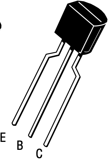
So, with the flat surface of the package facing you, the left lead is the emitter, the center is the base, and the right is the collector.
With this in mind, build the circuit below.

In this circuit, the DAC sends an input voltage across an LED and then across the transistor, the input coming into the collector. The emitter is grounded, which serves to ground the circuit, including the LED. The base of the transistor is controlled by digital output from the Arduino Uno. We are using a 10 kΩ resistor on this input, giving a current of about 500 nA, which is plenty for the transistor to be operating at saturation.
You will oscillate the voltage across the transistors using the sketch below.
#include <Adafruit_MCP4725.h>

#define MCP4725_ADDR 0x62

const int led1Pin = 12;
const int led2Pin = 7;
const int led3Pin = 2;

const int HANDSHAKE = 0;
const int LED1 = 1;
const int LED2 = 2;
const int LED3 = 3;
const int LED1_ASCII = 49;
const int LED2_ASCII = 50;
const int LED3_ASCII = 51;

bool led1PinState = LOW;
bool led2PinState = LOW;
bool led3PinState = LOW;

const int freq = 1;
const unsigned long sampleDelay = 20;
unsigned long lastSampleTime = 0;

Adafruit_MCP4725 dac;

void writePinState() {
  digitalWrite(led1Pin, led1PinState);
  digitalWrite(led2Pin, led2PinState);
  digitalWrite(led3Pin, led3PinState);
}


void setup() {
  pinMode(led1Pin, OUTPUT);
  pinMode(led2Pin, OUTPUT);
  pinMode(led3Pin, OUTPUT);

  writePinState();

  dac.begin(MCP4725_ADDR);

  Serial.begin(115200);
}


void loop() {
  unsigned long currTime = millis();
  if (currTime - lastSampleTime > sampleDelay) {
    uint16_t x = (uint16_t)(4095 * (1 + sin(2 * PI * freq * millis() / 1000.0)) / 2.0);

    dac.setVoltage(x, false);

    lastSampleTime = currTime;
  }

  // Check if data has been sent to Arduino and respond accordingly
  if (Serial.available() > 0) {
    // Read in request
    int inByte = Serial.read();

    if (inByte == LED1 || inByte == LED1_ASCII) led1PinState = !led1PinState;
    else if (inByte == LED2 || inByte == LED2_ASCII) led2PinState = !led2PinState;
    else if (inByte == LED3 || inByte == LED3_ASCII) led3PinState = !led3PinState;
    else if (inByte == HANDSHAKE) {
      if (Serial.availableForWrite()) {
        Serial.println("Message received.");
      }
    }

    writePinState();

  }
}
A couple things to note in this sketch.
I allow for input signals to be both single bytes representing an integer, like
1,2, or3, and for the same signal to be sent as ASCII text. In ASCII,1is character number 49, so if I type1as input in the Serial Monitor of the Arduino IDE, Arduino will read it in at bytes representing the number 49. Writing the code in this way facilitates me controlling the Arduino from the Serial Monitor or from Python.I use
led1PinState = !led1PinStateto toggle the state of the LED. Thus, each time I enter2, for example, LED 2 gets turned on or off.To switch the LED on, we send a signal using Arduino’s digital pins.
After building the circuit and uploading the sketch, either control which LEDs are on (and showing the oscillating illumination) via widgets on a dashboard or by hand-entering the numbers in the Serial Monitor. You will see that the transistors act as a switch, sending the input voltage across the LED when on and not while off.
A simpler way to make the LEDs flash on and off sinusoidally would be to use PWM directly from the digital pins of the Arduino. There is no need for transistors in that case. However, if we want to have an analog input to the LEDs, and we only have one DAC, the transistors make it possible to switch them on and off.