22. Protecting Arduino with Zener diodes
The input pins on Arduino Uno can handle a maximum voltage of about 5 V. If an input exceeds this limit significantly, it can damage the microcontroller. So far, we have used the Uno board itself to supply 5 V for all of our applications. It was therefore not possible to expose any of the pins to more than 5 V.
In the next lesson, we will use op amps, which require external power supplies. One of the power supplies is 12 V. It is therefore possible to expose the Arduino board to more than 5 V. You would never intentionally design a circuit that could do that, since you can’t do anything with more than 5 V on the input pins. You may, however, unintentionally build a circuit that could result in more than 5 V across a pin on the Arduino board.
There are many ways to protect against this. A simple approach is to use a Zener diode.
Zener diode
A Zener diode has a strongly nonlinear relationship between current and voltage (contrasted with the linear relationship of a resistor),shown in the plot below.
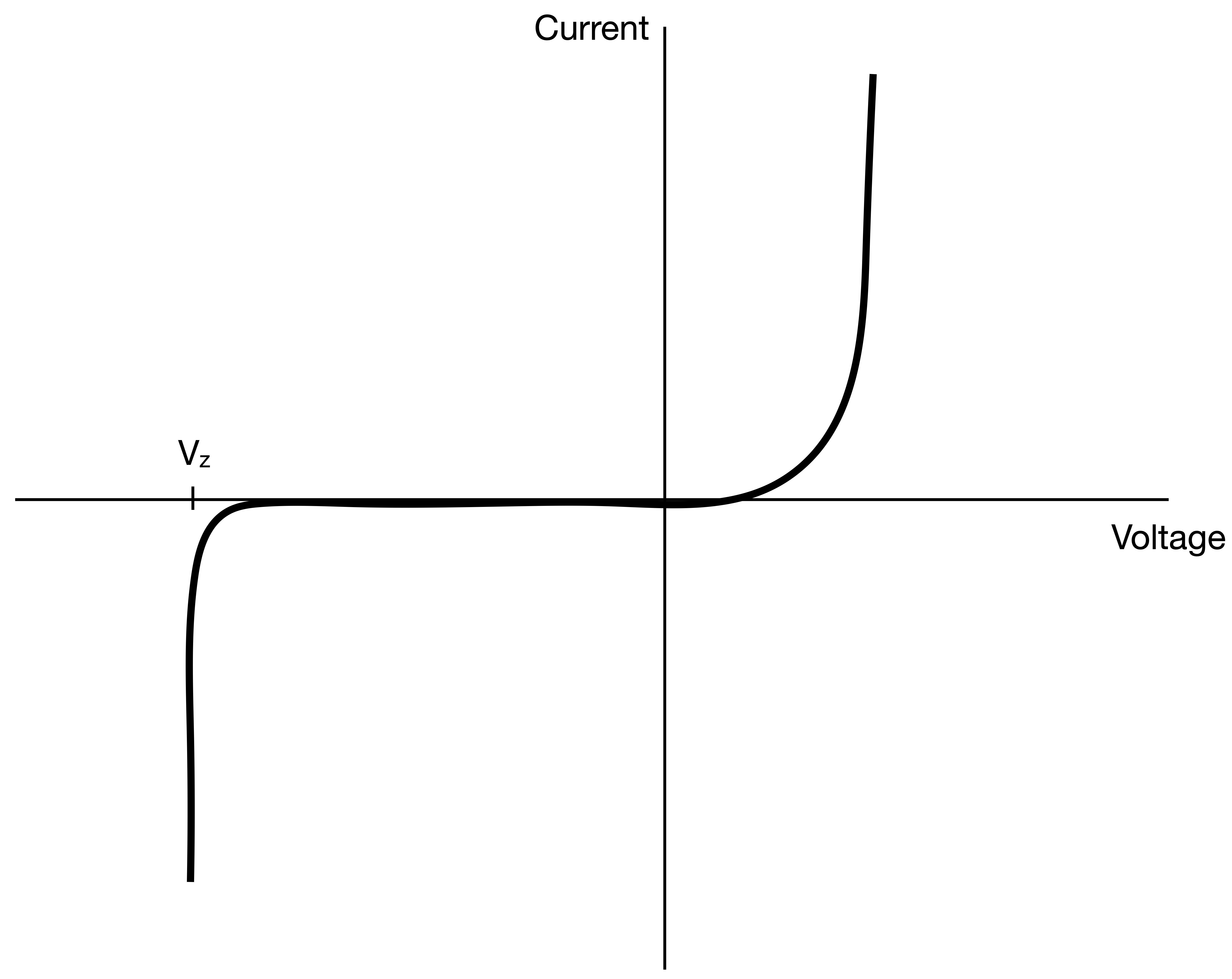
For a range of voltages, the current through the Zener diode is close to zero; it has very large impedance in that range. When the voltage across the diode is positive, the current can grow rapidly. In practice, we place the Zener diode in a circuit such that the voltage across it is negative (operating the Zener diode in reversed bias). In this regime, there is minimal current across the diode, the Zener diode breaks down. In other words, the voltage across it will not go much beyond \(V_z\), and significant current will flow across it. You can think of the Zener diode as a special resistor in this regime—it will reduce its resistance in response to an increasing voltage, thereby allowing the current flowing through it to ramp up rapidly.
This ability of a Zener diode to limit its voltage drop to approximately \(V_z\) is very useful. We can use this feature of the Zener diode to limit voltages of across parts of a circuit, importantly those across I/O pins on the Arduino or an external ADC.
Simple regulation of voltage supply with a Zener diode
Consider the circuit below, where \(V_\mathrm{in}\) is a voltage we want to be able to measure without destroying the microcontroller.
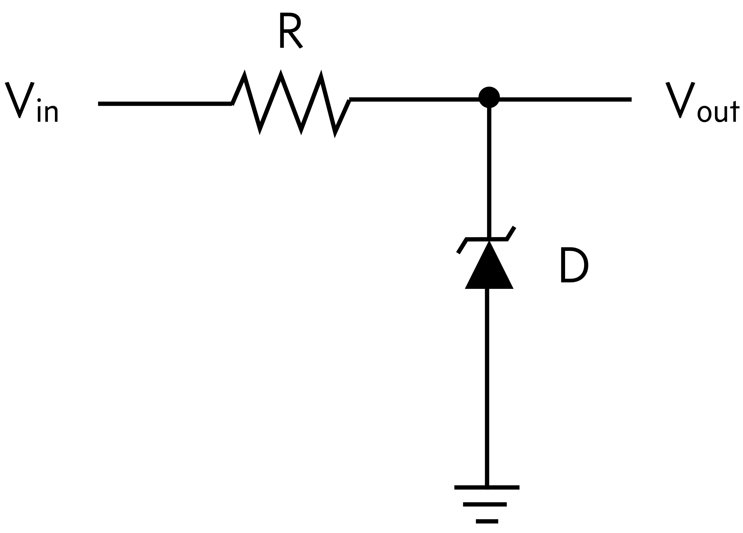
The simple circuit has the architecture of a voltage divider. Let \(R_z\) be the resistance of the Zener diode. Then, using our results from voltage dividers before,
\begin{align} V_\mathrm{out} = \frac{R_z}{R_z + R}\,V_\mathrm{in}. \end{align}
If the input voltage is smaller than the breakdown voltage \(V_z\), then the resistance of the Zener diode is very large, letting through essentially no current. Then, since \(R_z \gg R\), \(V_\mathrm{out} \approx V_\mathrm{in}\). If \(V_\mathrm{in}\) is above \(V_z\), then \(V_\mathrm{out} = V_z\), since the Zener diode will adjust its resistance so that the voltage drop across it is approximately \(V_z\). So, if you read \(V_\mathrm{out}\), either on board Arduino or on an external ADC, you will get \(V_\mathrm{in}\) below the breakdown voltage, above the breakdown voltage, your ADC device will only experience \(V_z\), thereby protecting it. Importantly, for \(V_\mathrm{in}\) near but not beyond \(V_z\) the finite, variable impedance of the Zener diode can lead to \(V_\mathrm{out}\) being a bit less then \(V_\mathrm{in}\), thereby affecting the accuracy of measured voltages.
But for our purposes, this design will suffice.
Given a possible range of \(V_\mathrm{in}\) (in our case the maximum is 12 V), and the ratings of the Zener diode, we are left to choose \(R\) in our design. To mitigate the negative effect of (2) above, we want to choose \(R\) to be as small as the Zener diode can handle. The Zener diode in your kit is a BZX79-C5V1,133. This particular Zener diode has a maximum power dissipation of \(P = 400\) mW and \(V_z\) between 4.8 and 5.4 V. Thus, the maximum current that can be allowed to flow through the Zener diode is \(I_\mathrm{max} = P / V_z \approx 75\) mA. To keep the current below this level, the resistance \(R\) must be at least \(R \ge (V_\mathrm{in}^\mathrm{max} - V_z) / I_\mathrm{max} \approx 100\) Ω. Even with this resistance, the Zener diode can get a bit warm, do I usually choose a resistance a bit higher. Nonetheless, this is a protective measure, and hopefully your circuit will not ever have \(V_\mathrm{in}\) above five volts, so this will not be a problem.
Follow along exercise 15: Demonstrating protection by a Zener diode
To demonstrate to yourself that this works, construct the circuit below.
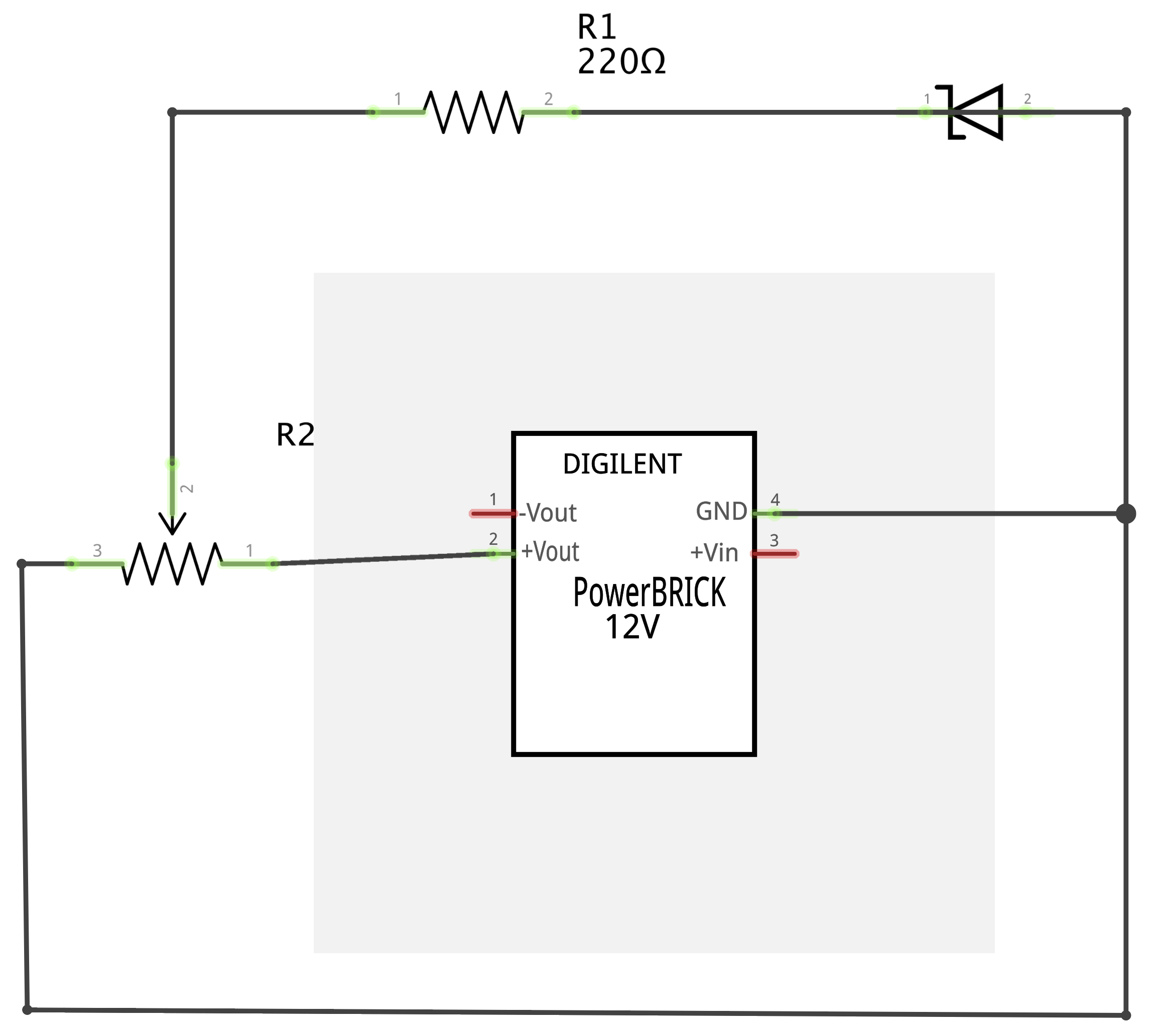
For convenience, here is the pictorial schematic.
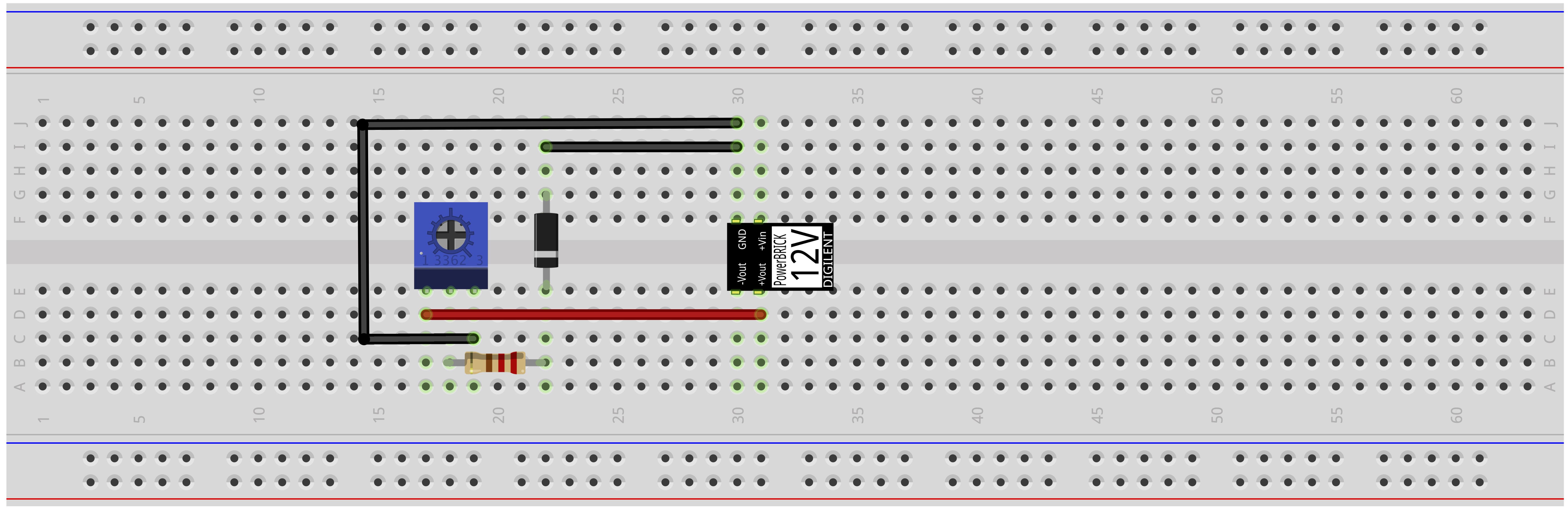
Note the direction of the Zener diode. In the Zener diode in your kit, the body is pink and the stripe is black. In the image above, the body is black and the stripe is gray.
You will need to plug in the PowerBRICK using the USB cable and power adapter in your kit.
Use the potentiometer to vary the voltage coming into the circuit. Use your multimeter to measure \(V_\mathrm{in}\) and \(V_\mathrm{out}\) for a set of various \(V_\mathrm{in}\). (Think: Which leads do you need to touch with your multimeter probes to measure these quantities?) Does the circuit work as advertised? Note that I have chosen a resistor with about twice as much resistance as theoretically needed.