21. Photoresistors, trimming, and ADC
You have learned some of the basics of building prototypes of electronic circuits. In this lesson, you will get considerably less guidance on the do-it-yourself exercise, and will have to rely on what you have learned so far and online tutorials and data sheets.
Photoresistors
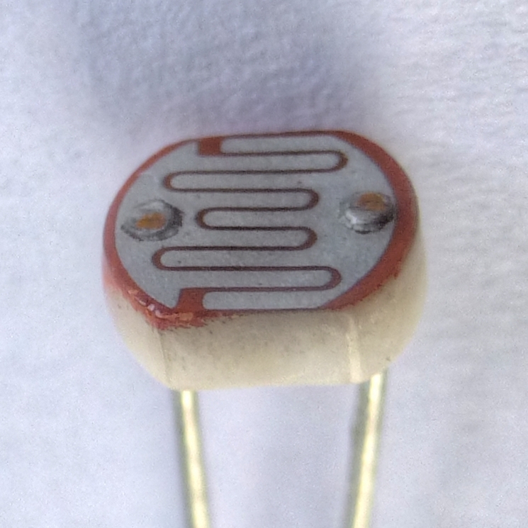
Optoelectronic devices are devices that can detect and control light. Our primary interest is detection, since we will be building a spectrophotometer. There are many optoelectronic detectors, including photodiodes, phototransistors, and photoresistors. A photoresistor (pictured below) is a resistor whose resistance is dependent on the intensity of light incident on its surface. The more light, the lower the resistance.

Image by Nevit Dilman,CC-BY-SA 3.0 licened.
By measuring the voltage across a photoresistor, we can get a measure of the amount of incident light. In the exercise below, you will measure exactly that (which you will also do when you build your spectrophotometer).
Trimming resistances
In the exercise below, you will likely set up voltage dividers. It helps to have good control over the resistances in the dividers. You have many different resistors in your kits, but what if you want to obtain a resistance you do not have? You can use a couple simple principles to do that.
Resistances in series result in resistance \(R = R_1 + R_2 + R_3 + \cdots\).
Resistance in parallel result in resistance \(R = \left(R_1^{-1} + R_2^{-1} + R_3^{-1} + \cdots\right)^{-1}\).
Point (2) means that resistors in parallel always have a lower resistance than the largest individual resistor.
Say you have an available resistor just below the value you want. You can trim the resistance up by adding small resistor or resistors in series to make up the difference.
Now say you have an available resistor just above the value you want. You can trim the resistance down by adding a small resistor or resistors in parallel to bring the total resistance down.
Do-it-yourself exercise 9: Photoresistors with ADC
The Arduino Uno has built-in six-channel 10-bit analog-to-digital conversion capability, available via pins A0 through A5. For many purposes, these are sufficient. However, if you want to have better resolution, you need a greater bit depth. Included in your kit is a 12-bit ADC breakout board which uses the ADS1015 ADC and also includes a programmable gain amplifier (PGA). As part of this exercise, you will need to read about this device and figure out how to use it to perform ADC. You can ask Google, but as a hint, the manufacturer of the breakout board, Adafruit, has useful material on their website, and the data sheet from Texas Instruments on the ADS1015 is also useful.
Your task is this: Build a circuit in which you measure incident light intensity on two photoresistors at the same time. Of course, you cannot measure incident light intensity directly, but rather will measure a related quantity, the voltage across a photoresistor. For your project, you will want to carefully calibrate the measured voltage versus incident light.
The voltage across each photoresistor should be read both by using the built-in pins on the Arduino Uno and by using the ADS1015. Reading the voltage in two ways will give you a way to check to make sure everything is working properly. You should make an app wherein the voltages can be monitored in real time.
You want to get the best resolution you can over a large dynamic range. Here are some hints.
Carefully read the information on the ADS1015. Here is a big hint that you will find: Unlike the ADC in the Arduino Uno, the ADS1015 can convert negative voltages. Its output is 12-bits, so the range of values is from –2048 to 2047. You should think carefully about how to take full advantage of the full range of numbers. Otherwise, if you are just using positive numbers, you only get one extra bit beyond the 10-bits in the built-in ADC. (Though in practice, you would probably use a 16-bit ADC, possibly the ADS1115.)
Given that you can get negative numbers coming into Python from Arduino, you need to allow for that. If you are screening the input data using regular expressions in your parser (as I did in the lessons), you have to include the minus sign in your pattern, for example like this:
re.compile(b"\d+|,|-").Think about how you can use voltage dividers to get the best dynamic range. The photoresistors in your kit have a resistance of about 50 to 100 kΩ depending on the light intensity.